Here we go again. It’s time to get
started on the much anticipated T040b Lifeboat station from Scalescenes. This
kit is the second part of the duo of the T040a 52ft Barnett Class Lifeboat and
a period Lifeboat house. I’ve been waiting for this kit for what seems like
forever. Having built the Lifeboat a couple of months ago, I’ve been eagerly
awaiting the release of this kit, to accommodate my lifeboat.
Anyhow enough
rambling, let’s crack on.
This kit is a
big one!!! (32 pages big) But after building the lifeboat, I’m pleased to get
my teeth into something a lot bigger.
|
|
|
Next, cut out all of the window openings
and run a marker pen around the raw edges. Then stick the window sheet to some
clear acetate. Set these aside for now.
|
|
|
|
|
|
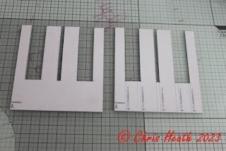
The substantial foundation is next. Cut
out the two Foundation A parts and glue them together. A tip I have at this
stage, is to get yourself a couple of pieces of 2mm card, and glue them
together, back to back. I use this as a spacer to check that the slots that are
cut into the foundation pieces are wide enough. All will become apparent
shortly. Repeat with Foundation pieces B C D and E.
|
|
|
|
|
|
Next, cut out and glue together back to
back print sides out, the two Foundation 1 pieces.
|
|
|
Cut out and glue together, the two
Foundation 2a pieces, and glue them over the top of their corresponding
Foundation 2b pieces. Don’t worry that there looks to be mistake here. It’s
supposed to look like this. Set these put these under a couple of heavy books
or weights to ensure that they glue securely.
|
|
|
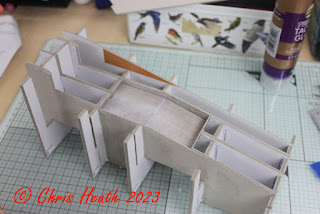
Next, start to assembly. On a level
surface, with the light blue guidelines facing the back, glue Foundation 1
squarely into Foundation A. This is where using that piece of 4mm card in the
slot earlier, makes sure that the pieces fit together. Use a square to make
sure everything is perpendicular.
|
|
|
|
|
|
Repeat the process for Foundations B C D
and E. Making sure to follow the instructions on which way the light blue
guidelines should be.
|
|
|
|
|
|
Next, with the printed sides facing
inside, test fit and glue the Foundation 2b pieces. As before, make sure
everything is square and perpendicular.
|
|
|
Cut out and lightly score on the red
line, the Well Floor. Introduce a slight angle. Dry fit this for now and cut
out both the upper and lower well walls. Test fit these. Then glue all three
components into place.
|
|
|
|
|
|
Next, cut out the two Foundation 3
sections. With the printed side facing inwards, glue these two parts into place
into Foundations A B C D and E. make sure everything is square.
|
|
|
|
|
|
Cut out and glue in place, the
foundation top 1 next. Make sure the this piece is central.
|
|
|
Next, cut out and glue into place the
Ramp Well Floor into place.
|
|
|
Cut out the Ramp B left and right
sections. Making sure the edges line up with the outside edge, glue into
place.
|
|
|
Now, I was left with an unsightly gap at
this stage (I’m sure it was of my own doing) but I just printed off another
page with Ramp Well Floor on, cut a section out, and glued it over the gap!
|
|
|
|
|
|
Next, cut out the and lightly score on
the red lines, the Back Wall. Test fit and glue into place. This is where that
what looked like a mistake, when gluing the two Foundation 2 a/b pieces together
becomes obvious. It helps to form the curve of the back wall.
|
|
|
Cut out the Back Wall cover layer and
glue over the top of the base layer. Smooth into place. Once in place cut out
the Ladder and glue into place.
|
|
|
|
|
|
Next, cut out both Ramp A Left and Right and glue them into place. Making sure to line the up with the outside edge.
|
|
|
Cut out and glue into place, the two
Cradle Well edges.
|
|
|
The last task for this session is to cut
out the Ramp Platform A and B sections. Glue the smaller section B to the back
of section A and then glue onto the ramp.
|
|
|
That’s it for now. The next part is to
fashion the winch. Which is quite a mean feat with my sausage fingers.
Until Next
Time………….


No comments:
Post a Comment